- C++ 79.4%
- C 19.9%
- PowerShell 0.5%
- Shell 0.2%
| docs | ||
| platformio | ||
| util | ||
| .gitattributes | ||
| .gitignore | ||
| CHANGELOG.md | ||
| HARDWARE.md | ||
| LICENSE | ||
| OneWire2.cpp | ||
| OneWire2.h | ||
| PocketOBI.ino | ||
| README.md | ||
| THIRD-PARTY.md | ||

PocketOBI
A standalone, screen-based reader and diagnostic tool for Makita LXT (18V) batteries, running on an ESP32-C3 — no PC required. It reads cell voltages, temperatures, charge count and error/lock state, and can reset false BMS lockouts to rescue packs that are still good.
PocketOBI is a standalone OBI client: it speaks the same Makita OneWire protocol documented by the Open Battery Information project, but as a self-contained handheld device with a TFT screen and a rotary encoder instead of a computer.
Created by The Repair Forge — follow the build on YouTube: https://www.youtube.com/channel/UCQL_-pcIEkrDPyljl3QPzcw
📺 Watch it in action
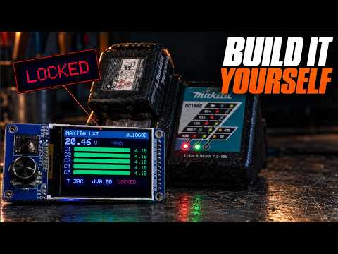
Full walkthrough — how it works, the reverse-engineering, and a live demo: https://youtu.be/57KsQQ7-Qd0
Project status — Step 1 (beta)
This is beta and a work in progress. Expect rough edges; experimentation is ongoing. Feedback and test reports (especially serial logs from real packs) are very welcome.
⚠️ Safety first. These packs contain lithium cells and up to ~21 V on B+. Never connect B+ to the ESP32. Resetting a BMS error only helps a pack whose cells are actually healthy (a false lockout). Do not force a pack with a genuinely bad/low cell back into service — it is a fire risk. Use this tool at your own risk.
Features
- Standalone reader with a menu-driven UI (rotary encoder + click, plus a secondary back button: short = back, long = home).
- Per-cell voltage bars with color-coded health (green / yellow / red) and imbalance detection.
- Pack voltage, estimated state of charge, two BMS temperature sensors, spread.
- Model, charge count, manufacturing date, capacity, error code, lock state.
- Automatic detection of standard vs older F0513 BMS generations.
- Error reset with before → after feedback (full test-mode + power-cycle sequence).
- Unlock / repair: rewrites the frame to lift a charger lockout on a pack whose cells are healthy — clears the charger-lock nybble and recomputes the charger-validated checksums, then writes the frame back. See below.
- Pack LED test (on/off).
- Raw debug view (ROM ID + message frame).
- PC bridge mode: acts as a USB↔OneWire adapter (drop-in ArduinoOBI), so the desktop Open Battery Information app works through PocketOBI. Dual use: standalone tester and PC adapter.
Architecture

(click for full size — full-resolution file in docs/architecture.png)
From the battery up: the Makita pack speaks over a single data wire; the bundled OneWire2 driver (reused from OBI) handles the custom Makita bit timings; the ESP32-C3 firmware is layered — protocol (frames + ENABLE, pack-type detection), data decode (bytes → cells / temperature / errors / lock), display (Adafruit GFX
- ST7789) and a small UI state machine — driving the TFT and, optionally, a USB PC bridge.
Hardware
| Component | Notes |
|---|---|
| ESP32-C3 SuperMini | any ESP32-C3 board with native USB |
| 2.4" SPI TFT, ST7789 (240×320) | + integrated EC11 rotary encoder module |
| Makita BL1830 LXT adapter | clips onto the 18V pack |
| 2 × 4.7 kΩ resistors | pull-ups for DATA and ENABLE (470 Ω also works) |
| USB-C power (power bank/charger) | powers the tool — NOT the battery |
Wiring

(click for full size — full-resolution file in docs/wiring.png)
Display + encoder module (2-in-1 TFT + EC11):
| ESP32-C3 | Module pin | Role |
|---|---|---|
| GPIO0 | SCL | SPI clock |
| GPIO1 | SDA | SPI data (MOSI) |
| GPIO10 | RES | reset |
| GPIO20 | DC | data / command select |
| GPIO21 | CS | chip select (active low) |
| 3.3 V | VCC | logic power |
| 3.3 V | BLK | backlight (or leave unconnected = always on) |
| GND | GND | ground |
| GPIO5 | A | encoder phase A |
| GPIO6 | B | encoder phase B |
| GPIO7 | PUSH | encoder push button |
| GPIO2 | KO | secondary button (short = back, long = home) |
Battery adapter (Makita LXT connector):
| ESP32-C3 | Battery pin | Role |
|---|---|---|
| GPIO3 + 4.7 kΩ pull-up to 3.3 V | Pin 2 — DATA | OneWire data |
| GPIO4 + 4.7 kΩ pull-up to 3.3 V | Pin 6 — ENABLE | enable (active high) |
| GND | main B- terminal | ground (sturdier than signal pin 5; same ground) |
| — | Pin 1 — B+ (18 V) | NEVER CONNECT |
Notes:
- Pull-ups: 4.7 kΩ is the reference value; 470 Ω was used successfully on a breadboard (on 3.3 V logic the pack loads the DATA line near the input threshold, so a stronger pull-up can help with long/messy wiring).
- ⚠️ Identify DATA/ENABLE by the ESP32 silkscreen labels ("3" / "4"), not by
the adapter's connector position. Some AliExpress adapters number their orange
connector from the opposite end, so DATA can land on what looks like "plot 6"
and ENABLE on "plot 2". Wrong plots = no comms (present = 0, all-
FF/00). - Power the tool from USB-C, never from the Makita pack (B+ is 18 V, and the BMS can cut its own output on error).
A carrier-PCB design (netlist, BOM, footprints, KiCad quick-start) is drafted in HARDWARE.md — not manufactured yet.
Build & flash
Arduino IDE
- Install the ESP32 board package (Espressif) via the Boards Manager.
- Install these libraries via the Library Manager:
- Adafruit GFX Library
- Adafruit ST7735 and ST7789 Library
- RotaryEncoder (by Matthias Hertel)
- (OneWire2 is bundled in this repo — nothing to install.)
- Open
PocketOBI/PocketOBI.ino. - Board: ESP32C3 Dev Module, USB CDC On Boot: Enabled.
- Upload.
Note: Arduino requires the sketch to live in a folder named
PocketOBI. If you downloaded a ZIP (GitHub adds a-mainsuffix), rename the inner sketch folder back toPocketOBIbefore opening it.
PlatformIO (VS Code)
A ready-made PlatformIO project is in platformio/:
cd platformio
pio run             # build
pio run -t upload   # build + flash
It mirrors the Arduino sources (the root PocketOBI.ino stays the source of
truth); details in platformio/README.md.
Usage
Power the tool over USB, connect DATA / ENABLE / GND to the pack (never B+),
and it reads automatically. Turn the encoder to navigate, click to select.
If the home screen shows "No battery found", check wiring and use
Menu → Read battery. "Comm error" / all-0xFF means the pack's BMS is not
responding (dead, or not an OBI-compatible pack).
Unlock / repair
Some packs refuse to charge even though their cells are healthy and balanced: the BMS stores a frame that trips the charger's lock. The Makita charger only validates three fields of the 32-byte frame:
- nybble 34 (byte 17, low) — the charger lock, must be
0; - CS0 (nybble 41) —
sum(nybbles 0–15) & 0x0F; - CS2 (nybble 43) —
sum(nybbles 32–40) & 0x0F.
The status byte (byte 19, e.g. 0xA5) and the reported temperatures are not
part of that check. The battery's own internal lock additionally checks CS1
(nybbles 16–31, per the rosvall protocol docs), so the repair recomputes all
three checksums. The Unlock / repair menu entry clears nybble 34, recomputes
CS0/CS1/CS2, writes the frame back (arm → write → store) and clears the internal
error register. The failure code (nybble 40, e.g. 0xF = dead) is never
cleared — a genuinely dead pack is not forced back into service. Manufacturing/status bytes are never touched, and if the frame
is already valid no write is performed.
⚠️ This writes to the BMS flash and is gated behind a confirmation screen. It only clears a false charger lockout on an otherwise-healthy pack; it never overrides the BMS's own fault protection. Never use it to force a pack with a bad or low cell back into service.
Note on temperature units
Temperatures are decoded as 1/10 K (T_C = raw / 10 - 273.15). This is now
corroborated by four independent sources: the
rosvall protocol docs, the
obi-esp32 encoding, and both sides of the
m5din-makita fork — its
reader ((raw / 10) - 273.15) and its BMS emulator ((T_C + 273.15) * 10).
The original Open Battery Information app decodes the same field as
Celsius x100; that appears to be the outlier. The unit is still not stated in
any official Makita document, so treat the absolute value as approximate, but the
1/10 K interpretation is the well-supported one. The dependable signal is relative: the
two sensors are shown side by side (e.g. 28/31, and in red when a value is
implausible), so a reading that is far off or that disagrees strongly with the
other flags a likely faulty thermistor.
The two sensors are reported by the BMS over the data line (there is no separate thermistor pin on the connector). The original protocol simply labels them "Sensor 1" and "Sensor 2" — which reading is the cell sensor vs the MOSFET sensor is not documented, and their physical placement on the BMS board is unknown. PocketOBI just shows both values; do not assume which is which.
Versioning
See CHANGELOG.md. The current version is shown on the
Version / info screen and defined as FW_VERSION in the sketch.
Credits
- Open Battery Information by Martin Jansson — the original project that documents the Makita protocol and provides the OneWire2 library. https://github.com/mnh-jansson/open-battery-information (MIT)
- ESP32-C3 wiring reference: the
obi-esp32port by appositeit. - Root protocol reverse-engineering: the rosvall/makita-lxt-protocol documentation (frame byte/nybble map, the three checksum ranges, per-type command sets) — the origin much of the LXT decoding traces back to.
- Unlock / frame-repair research: the synrais/Makita-LXT-Battery-Monitor-Unlocker project, which documented the frame byte map, the CS0/CS2 checksums, the charger-lock nybble and the arm/write/store opcodes. That repository ships with no license (all rights reserved), so none of its code is used here; PocketOBI's unlock feature is a clean-room reimplementation from those (unprotectable) protocol facts only, cross-checked against real battery dumps.
License
PocketOBI is licensed under the PolyForm Noncommercial License 1.0.0 — free to use, modify, and share for any noncommercial purpose (personal, hobby, repair, education, research). Commercial use requires a separate license. See LICENSE.
Bundled and reused third-party components keep their own licenses — see THIRD-PARTY.md. The bundled OneWire2 library and the upstream Open Battery Information project remain under the MIT license.
  ___         _       _    ___  ___ ___
 | _ \___  __| |_____| |_ / _ \| _ )_ _|
 |  _/ _ \/ _| / / -_)  _| (_) | _ \| |
 |_| \___/\__|_\_\___|\__|\___/|___/___|
=-=-=-=-=-=-=-=-=-=-=-=-=-=-=-=-=-=-=-=-=-=-=
       . No Guru Meditation required .
=-=-=-=-=-=-=-=-=-=-=-=-=-=-=-=-=-=-=-=-=-=-=